Flight Manual: Bookmark J 35J Draken 5.12024-04-04
Communication radios
J 35J has two radio transceivers for voice and data communication.
|
FR28 |
VHF 104.000–159.975 MHz and UHF 225.000–339.950 MHz with FM and AM modulation Main radio for voice communication, backup radio for data messages. |
|
FR21 |
VHF 104.000–159.975 MHz with AM modulation Main radio for data messages, backup radio for voice communication. |
In this simulation FR28 corresponds to COM1 and FR21 to COM2. Both radios support all frequencies between 104.000 and 339.975 MHz. AM/FM modulation is not implemented in Prepar3D.
The radio panels on the left side console also include a Collins-style VHF tuning unit for VOR navigation. This unit was not present in the real 35J.
The radios are connected directly to the main electrical bus and have no master switch.
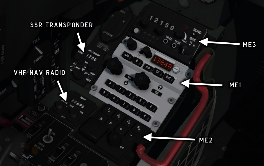
Fig. 44 - J 35J radio control panels
Radio control panel ME3
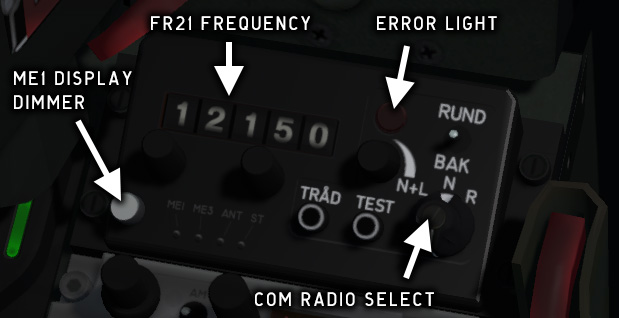
Fig. 45 - Radio control panel ME3
The ME3 panel is used to select radio modes and to manually set frequency for FR21 (COM2).
N+L/N/R
Radio mode select, see table below
RUND/BAK
Antenna selector (not functional)
TEST
Press for 1 KHz test signal
TRÅD
Wired ground com (not functional)
|
Mode |
Real J 35J |
Prepar3D |
||
|---|---|---|---|---|
|
FR28 |
FR21 |
COM1 |
COM2 |
|
|
N+L |
Voice - ME1 121.50 MHz monitored |
Data - ME2 |
ATC set by ME1 |
121.50 MHz |
|
N |
Set by ME1 |
Disabled |
ATC set by ME1 |
Receiving only |
|
R |
Disabled |
Set by ME3 |
Receiving only |
ATC set by ME3 |
The error light indicates radio failure.
Radio control panel ME1
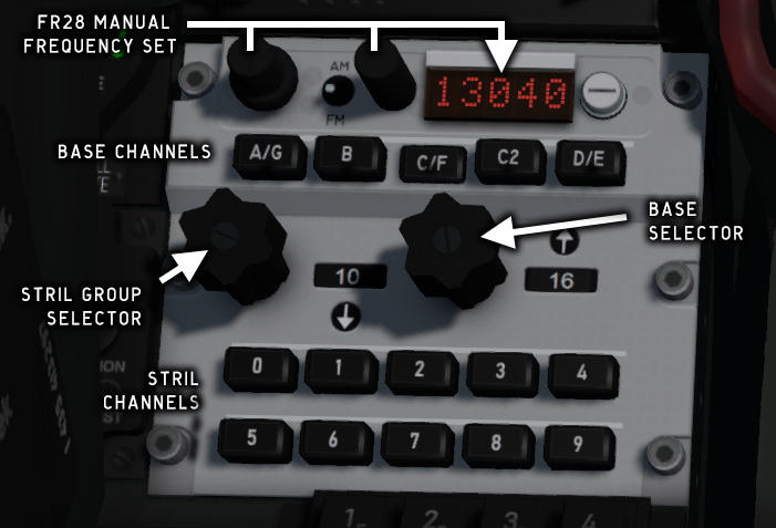
Fig. 46 - Radio control panel ME1
The ME1 panel controls FR28 (COM1).
The BASE selector and channel keys are used in combination to select one of 350 preset channels for TWR, TMC, etc. at 69 Swedish air bases. See Appendix 3: FR28 Radio channels.
The STRIL group selector and channel keys are used to select UHF channels.
When the minus key (–) is pressed, the com frequency is set manually with the two knobs to the left of the LED frequency display.
The FM/AM switch has no function in this version.
Accepting an ATC frequency in Prepar3D will change the current frequency setting. The new frequency will be shown on the display.
Radio control panel ME2
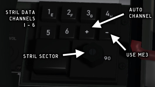
Fig. 47 - Radio control panel ME2
The ME2 control panel is used to select STRIL data channels for FR21. If the plus key is pressed, the data channel will be selected automatically. If the minus key is pressed, ME3 will set the data channel.
STRIL is not implemented in this simulation, so this panel has no function.
PN-837/A SSR transponder
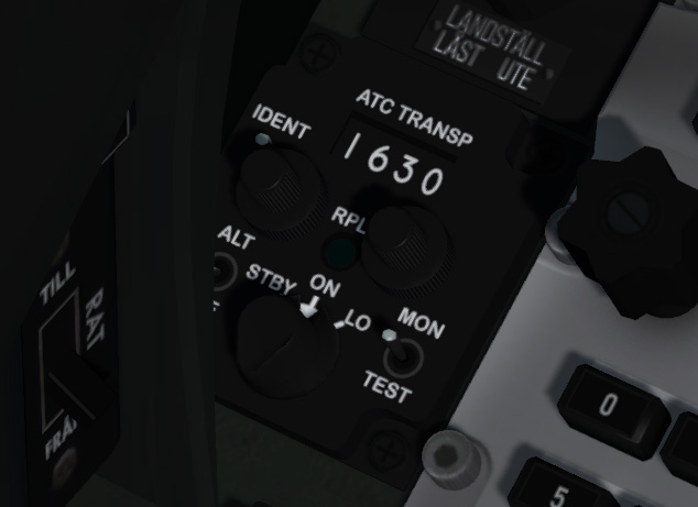
Fig. 48 - PN-837/A SSR transponder
The PN-837/A SSR transponder operates in the civilian modes 3/A and C.
STBY
Transponder on but not transmitting
ON
Normal mode (default)
LO
Transponder sensitivity reduced with -14dB
RPLY
LED indicator for query/reply transmission
IND
Push to enhance signal from aircraft for identification
ALT/OFF
Mode C altitude transmit on/off (not used)
MON/TEST
MON = RPLY indicator lit on query/reply
TEST = Test RPLY indicator (steady light)
Center position = query/reply function disabled
PN-79 IK transponder
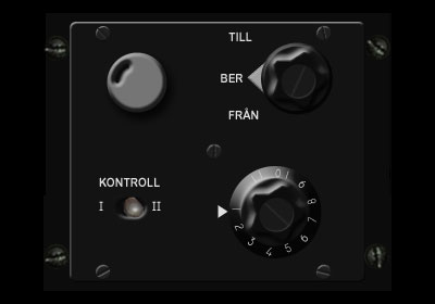
Fig. 49 - PN-79 transponder
The PN-79 transponder which is located on the right side console is a military IFF unit operating in encrypted mode. It has no function in this simulation.
Copyright © 2001–2024 Bookmark AB