Flight Manual: Bookmark J 35J Draken 5.12024-04-04
Instrumentation
Cockpit layout overview
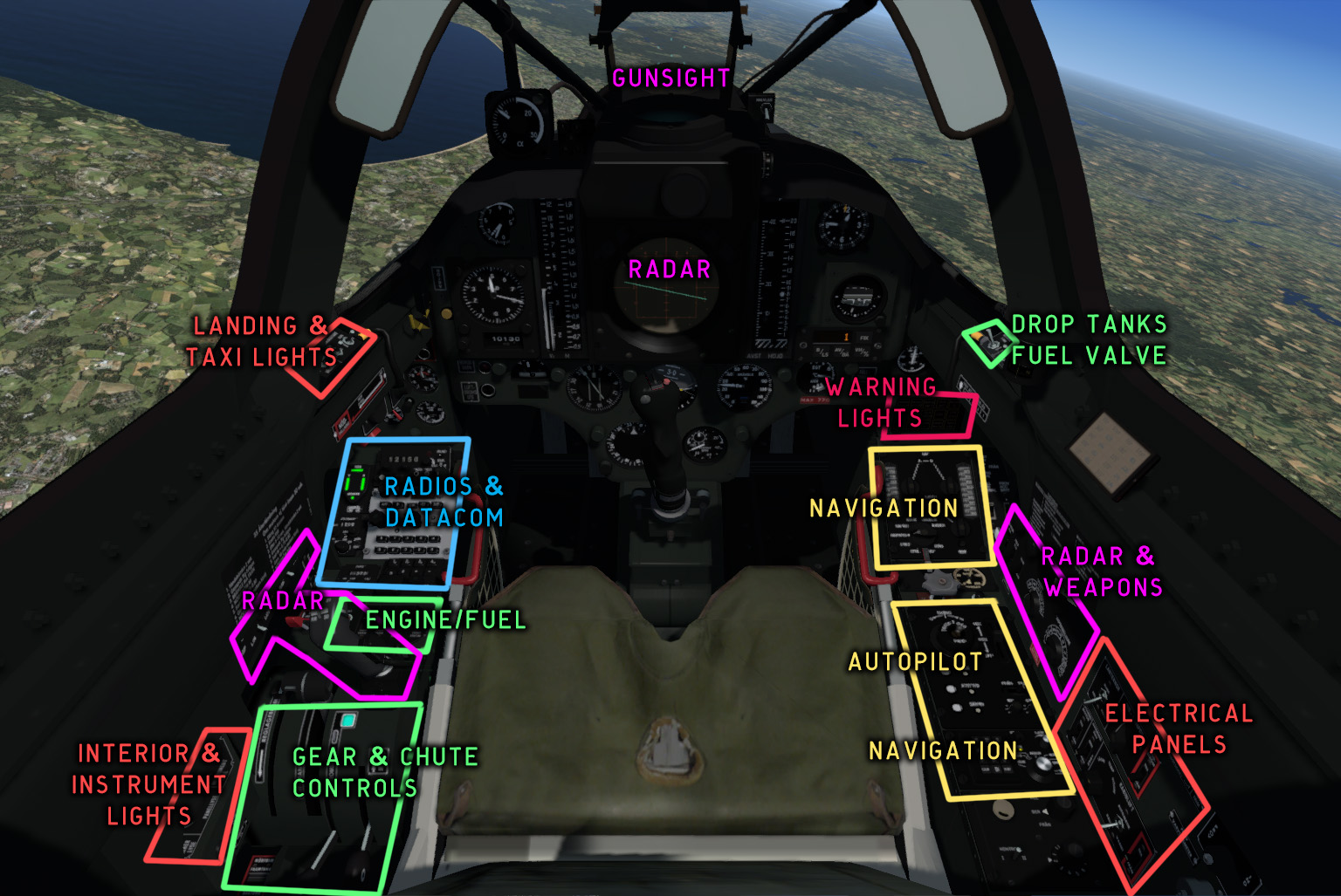
Fig. 30 - J 35J cockpit overview
Flight data system
The main altitude and airspeed indicators are controlled by the flight data system.
The flight data system consists of a data I/O unit, a Central Processing Unit (CPU), sensors, monitors, control panels and indicators for airspeed, altitude, navigation and targeting data. The CPU processes signals from sensors and monitors, radar and data link, and presents information on the various indicators and on the radar screen.
Main altimeter
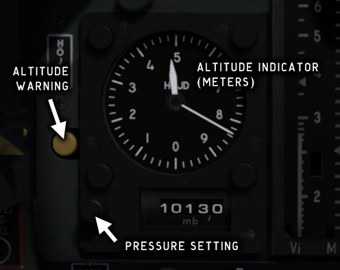
Fig. 31 - Altimeter
The altimeter shows the pressure altitude in meters, calculated by the flight computer. The needles are driven by an electrical stepper motor, which means that needle movement is not fluid but in small increments and with a slight delay.
To set the altimeter, place the cursor on the pressure setting knob and rotate the mouse wheel. Pressure setting is in millibars (hPa).
Airspeed/Mach indicator
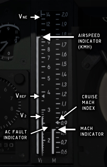
Fig. 32 - Airspeed/Mach indicator unit
The Airspeed/Mach Indicator is controlled by the CPU, which reads the nose pitot tube pressure.
The Mach scale is linear between M 0.5–2.0 and has an index at cruise Mach (M 0.9).
The Vi scale is linear between 150 and 350 kmh and logarithmic from 350 to 1400 kmh. The scale has indices for V2 (270 kmh), Vref (375 kmh), and VNE (1350 kmh).
A white rectangular field on the lower part of the airspeed scale indicates AC bus failure. The indication will disappear when the alternator bus is switched on and engine speed is at least 28 %.
Backup altimeter
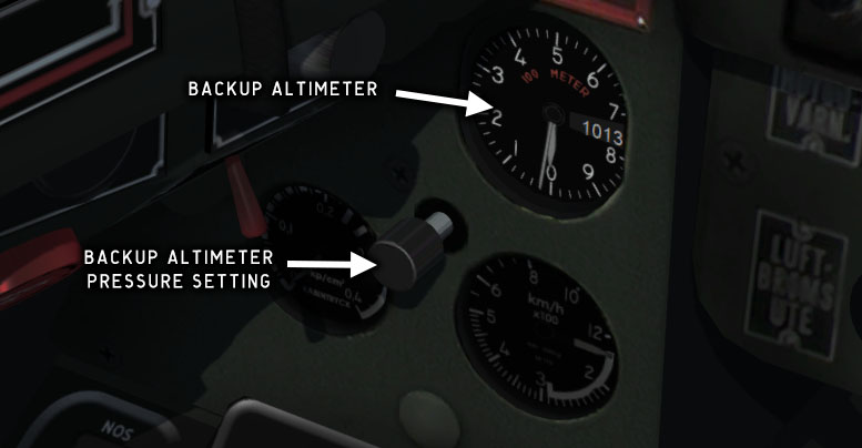
Fig. 33 - Backup altimeter
The backup altimeter is located on the left knee panel. The indicator is mechanical and directly fed from an aneroid. It is completely separate from the main altimeter and has its own pressure setting.
Backup attitude indicator
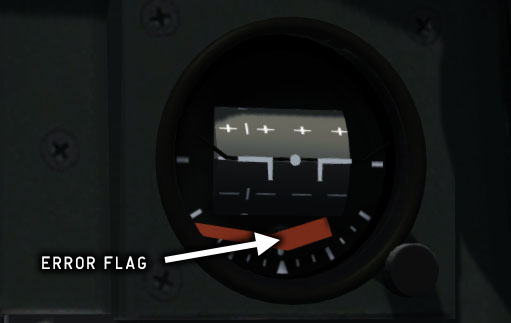
Fig. 34 - Backup attitude indicator
The backup attitude indicator is connected to a separate gyro and provides attitude information in case of a malfunction of the FLI 35 system.
Backup airspeed indicator
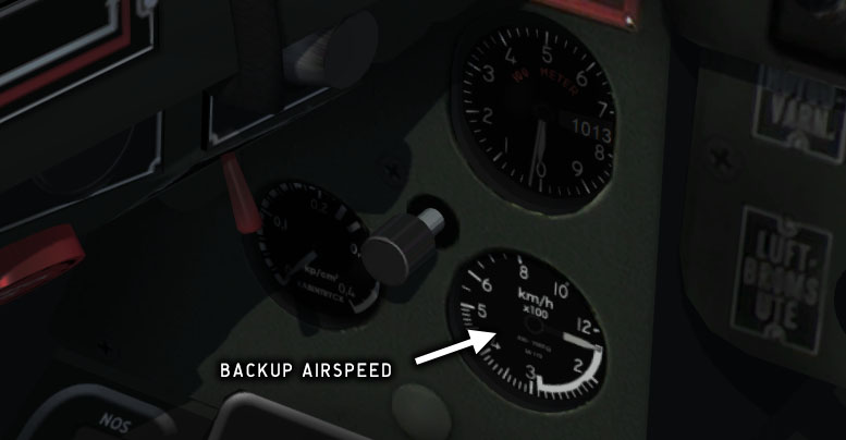
Fig. 35 - Backup airspeed indicator
The backup ASI is located on the left knee panel. It shows indicated airspeed from 150–1200 kmh. The backup ASI is completely mechanical and is connected to the stab fin pitot tube, while the main ASI via the flight computer is connected to the nose pitot.
AOA indicator
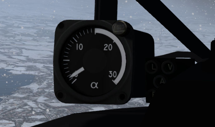
Fig. 36 - AOA indicator
The AOA indicator shows the current alpha angle of attack, which is the angle between the wing chord line and the current movement vector. Drag increases quickly with increasing alpha angle, so this indicator is crucial for maintaining control of the aircraft.
The Stall warning system will alert the pilot if the angle of attack exceeds a limit value.
Superstall (total loss of lift) will occur at AOA >18.
G-force indicator
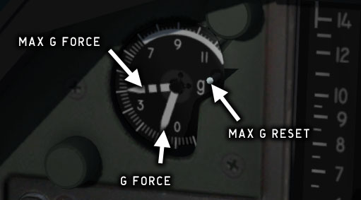
Fig. 37 - G-force indicator
The G-force indicator, or G-meter, shows acceleration force in the range -1.5 to +11.5 G. The indicator has a maximum needle which is reset by pushing the reset button on the right side of the meter.
An acoustic warning signal is triggered at approximately +6 G.
The G-force indicator is disconnected when the aircraft is on the ground.
Chronometer
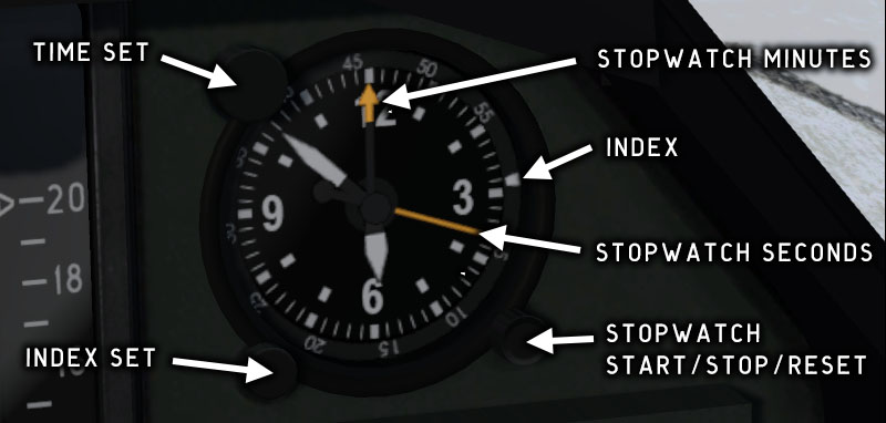
Fig. 38 - Chronometer
The aircraft chronometer is electrical and shows the current local time in hours/minutes. It has a stopwatch function and a moving index used to monitor flight time.
Before take-off, turn the index ring to align the index with the minute hand. The duration of the flight can then be read from the position of the minute hand vs. the index.
The stopwatch pushbutton will successively start, stop, and reset the stopwatch.
Cabin pressure indicator
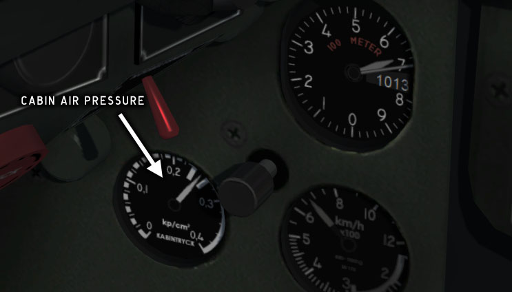
Fig. 39 - Cabin pressure indicator
The cabin pressure indicator is located on the left knee panel. It shows the pressure difference between ambient pressure and cabin pressure.
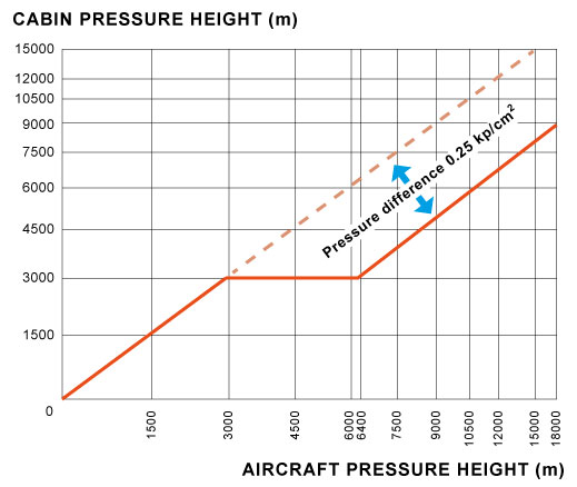
Cabin air pressure is regulated by a pressure regulator. The pressure difference should be zero up to 3000 m altitude, and then increase with altitude to a maximum of ~0.25 kp/cm2 (24.5 kPa) at 6400 m.
If the pressure difference exceeds 26 kPa, the KABINTRYCK warning light will be lit.
Copyright © 2001–2024 Bookmark AB