Flight Manual: Bookmark J 35J Draken 5.12024-04-04
Systems
Hydraulic system
The hydraulic system has three pumps feeding two circuits:
|
Circuit |
Pump |
Pressure |
Consumers |
|---|---|---|---|
|
I |
1 + 2 |
210 kp/cm2 (20 MPa) |
Gear, wheel brakes, nozzle, speed brakes, autopilot, control surface servos |
|
II |
3 |
210 kp/cm2 (20 MPa) |
Nose gear steering, control surface servos |
Each hydraulic circuit has a corresponding low pressure warning light:

|
Hydraulic pressure in circuit I less than 5 MPa |

|
Hydraulic pressure in circuit II less than 15 MPa |
When the engine is not running and the aircraft is motionless there is no hydraulic pressure. All control surfaces (including air brakes) are inoperable, and the elevons will be fully deflected downwards. When the engine spools up, the elevons will slowly rise to neutral position and all control surfaces become operable.
If the pressure in circuit II falls below 17.5 MPa, a backup hydraulic pump driven by a ram air turbine, the Emergency Power Unit (EPU), is automatically deployed. The backup pump will supply enough hydraulic pressure for the control surface servos (provided that the aircraft has enough airspeed). The EPU is automatically retracted when the pressure in circuit II exceeds 18.1 MPa.
At ground idle, large stick movements may cause the pressure in circuit II to momentarily fall below the threshold value, which will set off the HYDR II warning light and extend the EPU. This is normal and not a hydraulic system fault.
Wheel brakes
The wheel brakes are hydraulic self-adjusting anti-lock disk brakes. Normal brake pressure is 210 kp/cm2 (20 MPa). At least 60 kp/cm2 (5.9 MPa) is needed for effective braking. Brake pressure is provided by hydraulic pumps 1 and 2.
The hydraulic pressure in the brake circuit is shown by the brake pressure indicator on the right knee panel. It should always indicate normal pressure (210 kp/cm2), with a very slight dip when brakes are applied. If the indicator shows zero pressure, the brake circuit is damaged.
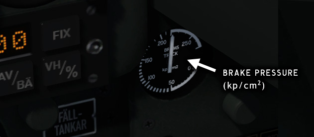
Fig. 68 - Brake pressure indicator
Extending gear at high airspeed may damage the wheel brake hydraulics. Do not extend the gear if airspeed exceeds 500 kmh.
In Prepar3D the anti-skid brake function is disabled by default. In this simulation it is always enabled.
Electrical system
Specifications
|
Electrical system specifications |
|
|---|---|
|
Alternator |
200 VAC/400 Hz/20 kVa |
|
Emergency alternator |
200 VAC/400 Hz/3.5 kVa |
|
Power consumption (typical) |
16 kVa |
|
Battery |
24 V/6.5 Ah |
| Bus name | Voltage | BATT | ALT |
EPU |
|---|---|---|---|---|
|
Hot Battery Bus |
24 VDC |
X |
|
|
|
DC Main Bus |
29 VDC |
X |
X |
X |
|
DC Normal Bus |
29 VDC |
|
X |
|
|
AC Main Bus |
3 x 200 VAC |
|
X |
X |
|
AC Normal Bus |
3 x 200 VAC |
|
X |
|
|
Instrument Bus |
3 x 45 VAC |
|
X |
|
The alternator is connected directly to the engine turbine shaft and has a regulator which keeps AC voltage and frequency constant regardless of engine speed.
Before the engine has been started, electrical power is normally supplied by an APU (Auxiliary Power Unit). Starting can also be done using only the aircraft battery as power source. In this version the APU is not implemented, and the battery is used for starting.
A backup alternator driven by a ram air turbine supplies power to the Main and Instrument buses in case of engine failure. See Emergency Power Unit (EPU).
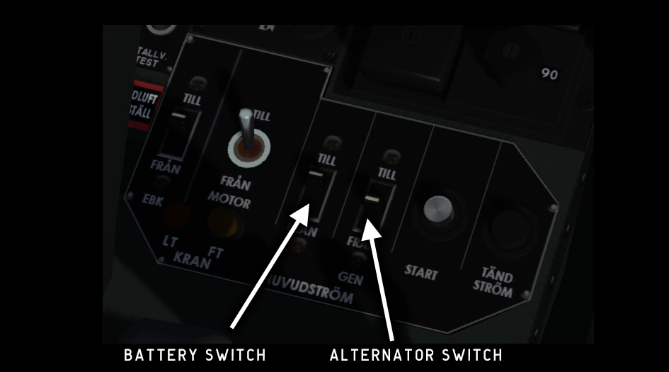
Fig. 69 - Engine control panel – electrical bus switches
Electrical failures
DC bus failures are indicated by the ELFEL warning light on the warning lights panel. This warning light will also be lit if the backup alternator is engaged.
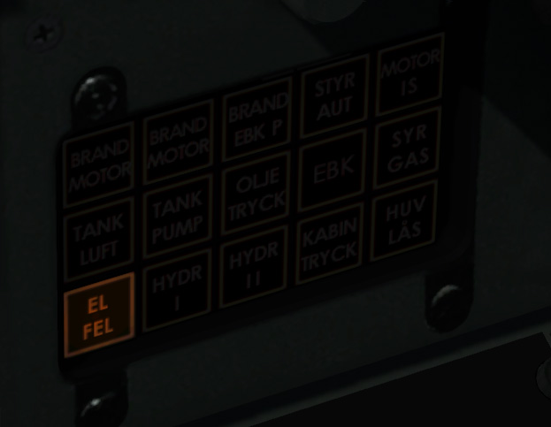
Fig. 70 - DC bus failure warning light
AC bus failures are indicated by a mechanical indicator on the Airspeed/Mach Indicator. If the white field is visible it means that AC power is not available.
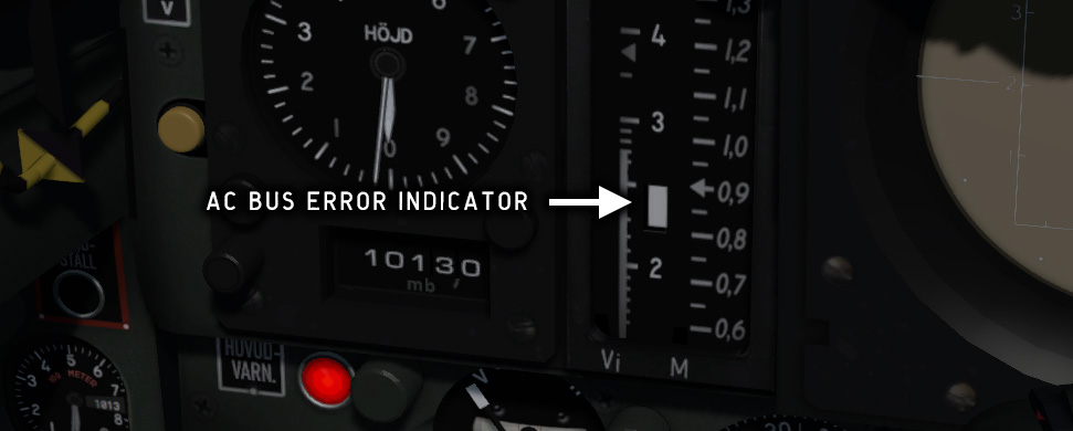
Fig. 71 - AC bus failure indicator
Electrical panels
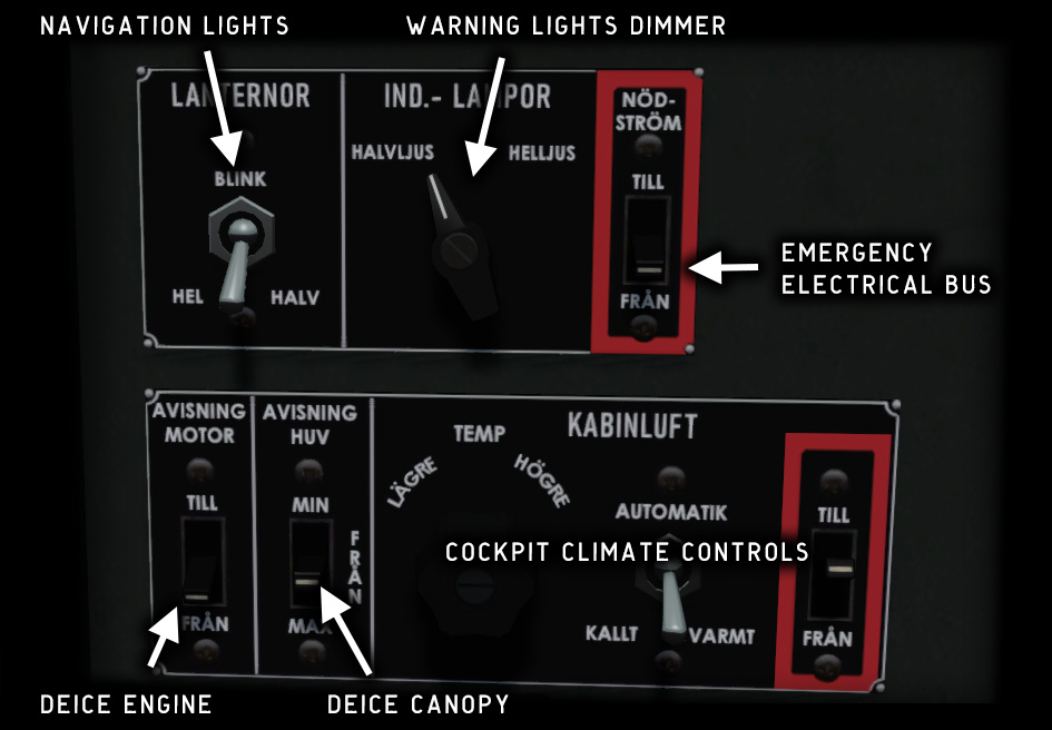
Fig. 72 - Electrical system control panels
LANTERNOR
Navigation lights. Four-way switch, center position is OFF.
HEL = bright, HALV = dimmed, BLINK = blinking (seldom used).
IND LAMPOR
Dimmer for all warning and indicator lights.
HALVLJUS = dimmed, HELLJUS = normal.
IND LAMPOR PROV
Push to test all warning and indicator lights.
NÖDSTRÖM
Emergency electrical bus toggle.
See also Emergency Power Unit (EPU).
AVISNING MOTOR
Engine de-ice. Use only before take-off.
MOTOR IS warning light is lit when activated.
AVISNING HUV
Canopy de-ice. Three-way switch, center position is OFF.
KABINLUFT
Cockpit climate control panel. Not functional in this version.
Circuit breakers
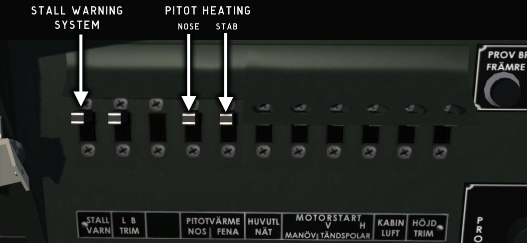
Fig. 73 - Circuit breaker panel
All electrical circuit breakers should be ON (up) at startup, although only three of them have any function in this version. The first four circuit breakers should be switched off at shutdown, the other (covered) circuit breakers are normally always left on.
Interior lights
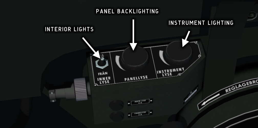
Fig. 74 - Interior lights panel
Instrument lighting and panel backlighting can be controlled individually with two dimmers on the left side of the cockpit. A toggle switch on the same panel controls the interior lights in the cockpit.
INNERLYSE
Interior lights
PANELLYSE
Panel backlighting
INSTRUMENTLYSE
Instrument lighting
Emergency Power Unit (EPU)
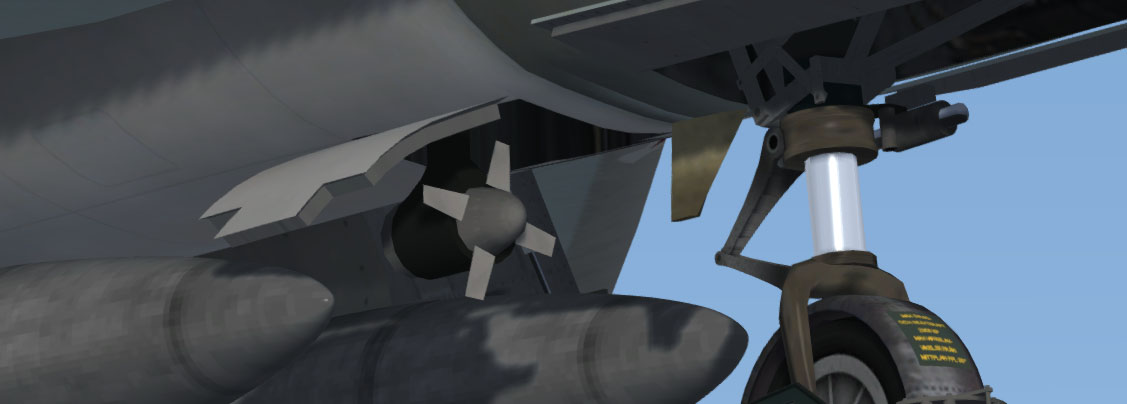
Fig. 75 - Emergency power unit
The Emergency Power Unit (EPU) is a ram-air turbine driving a backup alternator and a hydraulic pump. The alternator supplies 3.5 kVA and is connected to the electrical system bus when the EPU is deployed. The hydraulic pump has enough capacity to supply the most crucial functions.
When the hydraulic pressure drops below the threshold value and/or the AC bus is powerless, the EPU will be deployed and the electrical system will be connected to the emergency bus.
The emergency bus can be connected manually by toggling the NÖDSTRÖM switch. When this switch is on, the EPU will be deployed and the electrical system warning light ELFEL will be lit. This switch should be off under normal flight conditions.
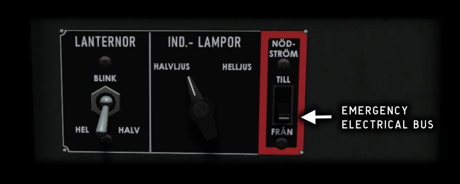
Fig. 76 - Emergency bus switch
The EPU will only supply electrical and hydraulic power if airspeed is at least 100 kmh (54 kts).
Fuel system
The fuel system consists of a low pressure system which includes the fuel tanks, fuel pumps and distribution system, and two high pressure systems that include fuel injection pumps, regulators and nozzles for the engine and afterburner.
The low pressure fuel system is controlled with valve switches on the engine control panel, while the high pressure system is controlled by the throttle handle.
The purpose of the low pressure fuel pumps is to raise the fuel pressure to a suitable level for the engine injection pump. The low pressure fuel pumps are powered from the AC bus and will only work when this bus is powered by an APU or the EPU. A separate start pump which is powered from the DC battery bus is used when starting the engine on battery.
Fuel tanks
J 35J has two internal tank groups with a total capacity of approximately 2700 litres. Each tank group also has a small buffer tank to facilitate fuel flow in inverted flight. >Two external tanks with 525 litres each can be fitted under the fuselage.
The 35J model could optionally be fitted with two additional drop tanks on the
wet
outer wing pylons. These tanks were normally only used for ferrying
missions. Wing tanks are not implemented in Draken 5.0.
The external tanks are jettisoned with the Drop Tanks 1 command. See also Drop tanks.
In Prepar3D the main tank groups in Draken are represented by Center and Center 2, the buffer tanks by Left Aux, and the drop tanks by External 1 and External 2.
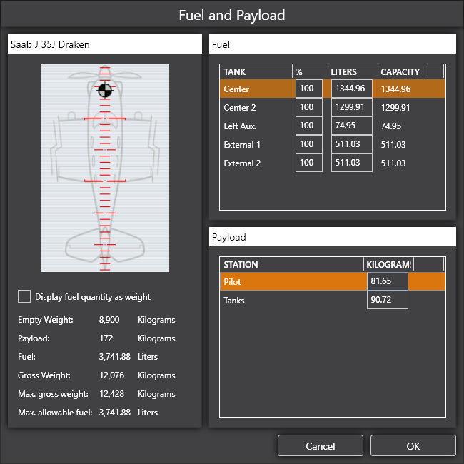
Fig. 77 - Prepar3D Fuel and Payload dialog
Fuel control
The Main Fuel Valve and Afterburner Fuel Valve switches on the Engine Panel control the low pressure fuel valves for engine and afterburner. Both switches must be ON during flight. The LT indicator light will be lit when either of these switches are OFF.
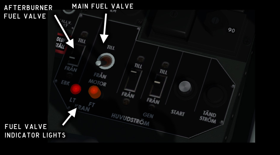
Fig. 78 - Fuel controls on engine panel
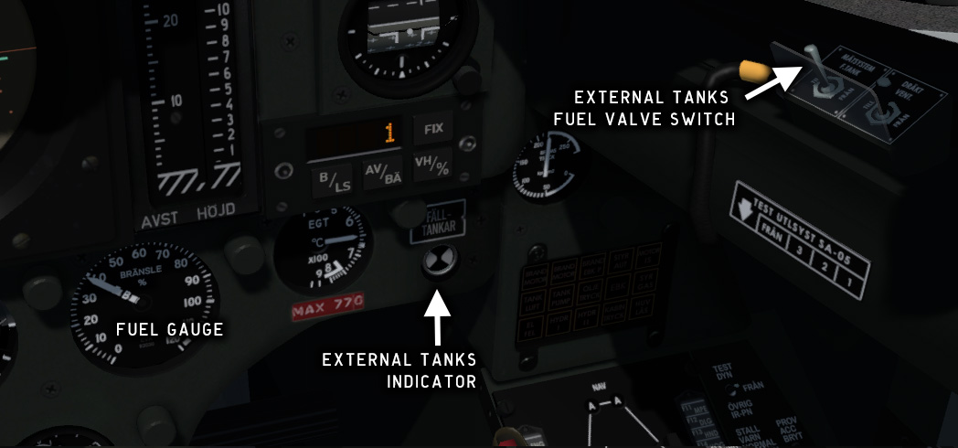
Fig. 79 - Front panel and valve switch
The Drop Tanks Indicator shows two white fields when the drop tank fuel valve switch is ON and there is fuel in the external tanks.
The drop tank fuel valve switch (MÄTSYSTEM FTANK) controls the low pressure fuel valves for the external tanks.
When the drop tank fuel valve switch is OFF, fuel will be supplied from the main tanks, alternating between front and rear groups to maintain the center of gravity. The fuel gauge needles for the forward (F) and rear (B) tank groups should not differ more than 5%.
When the drop tank fuel valve switch is ON, fuel will be supplied from the external tanks. The fuel gauge indicates remaining fuel in the external tanks, with 40% as maximum (80% with wing tanks). When the external tanks are empty or the drop tank fuel valve switch is OFF, the drop tank fuel valves close and the main tank valves open. The fuel gauge will automatically switch to measuring the main tanks, and the white fields on the Drop Tanks Indicator will disappear.
Engine
The engine in J 35J is a Volvo Flygmotor RM6C, which is an upgraded license-built Rolls-Royce Avon 300 Mk 60 turbojet with a Swedish single-stage EBK-67 afterburner.
The afterburner adds thrust to the engine by injecting additional fuel into the exhaust section. The ignited fuel raises the exhaust gas temperature, which increases the exhaust gas volume and speed. The exhaust nozzle area is widened when the afterburner is active to prevent the exhaust gas speed from exceeding Mach 1.
The engine control panel is located beside your left knee in the cockpit, just in front of the throttle lever. The panel is described in Before starting the engine and Starting the engine.
The alternator switch is spring-loaded. Push UP to switch the alternator ON. Push DOWN to switch it OFF.
The AC bus relay will only be actuated when engine speed is above 30 %. If engine speed falls below 27 %, the relay will drop and an AC bus error is indicated.
Engine control panel
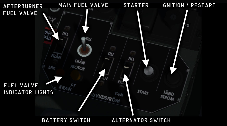
Fig. 80 - Engine control panel – overview
Exhaust temperature control
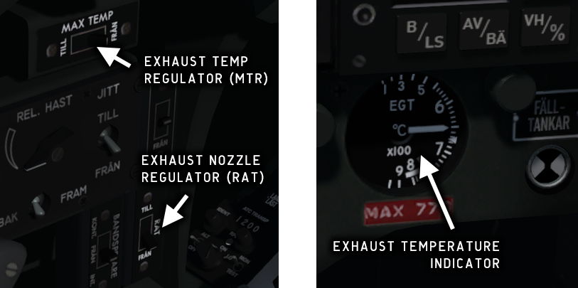
Exhaust gas temperature regulator (MAX TEMP/MTR)
The exhaust gas temperature regulator automatically reduces fuel flow to the engine to protect the engine from damage by overheating if EGT exceeds 750° C.
The regulator should normally be enabled (TILL), but can be disabled (FRÅN) to prevent loss of thrust during combat or under critical conditions.
The MTR system is not simulated in this version.
Exhaust nozzle regulator (RAT)
The exhaust nozzle regulator opens the exhaust nozzle eyelids fully to prevent overheating when the aircraft is on the ground and the throttle is at ground idle. The EBK warning light will be constantly lit in this mode. The nozzle will revert to the normal position once the throttle is above ground idle.
The RAT function should normally be enabled (TILL). It is automatically disabled when the aircraft is airborne.
The RAT function should not be confused with the ram air turbine, which is often abbreviated RAT but is here referred to as the EPU (Emergency Power Unit).
Landing gear
The landing gear consists of a main gear, a nose gear, and a spurwheel. The spurwheel protects the tail end as Draken has a very high attitude on landing. The landing gear is normally extended and retracted using hydraulic pressure from hydraulic circuit I, see Hydraulic system.
The main and nose gear are locked mechanically in both the extended and retracted positions. The spurwheel is hydraulically locked in the extended position and held in place by the spurwheel hatches when retracted.
A mechanical lock prevents the gear lever from being moved from the "gear extended" position if the throttle is at less than 90%.
The lights on the Gear Indicator are lit when the respective gear mechanisms are locked in the extended position.
The Gear Warning light (orange) blinks while the gear is being extended or retracted. It will also blink if the gear is not extended when airspeed is less than 450 kmh at less than 1450 m altitude and throttle is less than 85–90%.
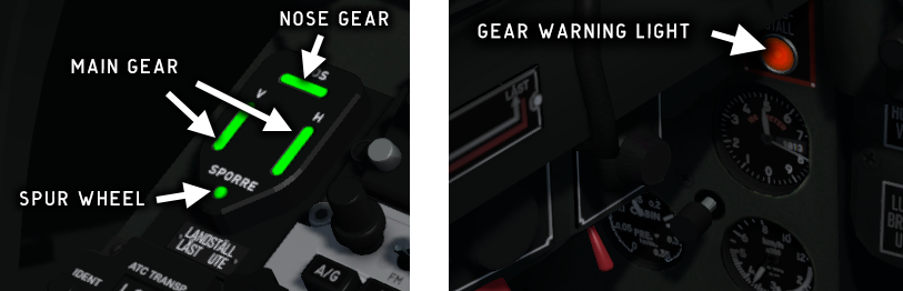
Fig. 82 - Landing gear indicator and warning light
If hydraulic pressure in the gear circuit is lost, the gear can be extended using gravity and then locked using compressed air from an accumulator. The pneumatic lock is activated with a lever on the left side console. See also Hydraulic system failure.
Stall warning system
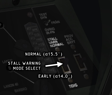
Fig. 83 - Stall Warning System
The Stall Warning System will warn the pilot when the angle of attack of the wing is approaching a critical value.
The system has two modes that can be selected from a panel on the right side console. In NORMAL mode, the stall warning alert will sound at AOA = 15.5, and in EARLY mode at AOA = 14.
Stall warning test
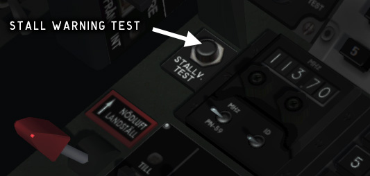
The STALLV. TEST button on the left side console can be used to test the stall warning system. Pressing this button will force the angle of attack indicator to just below the stall warning value. Applying back pressure at this point should trigger a stall warning.
Oxygen system
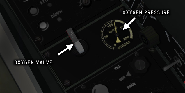
Fig. 85 - Oxygen control panel
The oxygen system supplies a mixture of oxygen and air to the pilot's breath mask. The mixture is automatically regulated depending on the cockpit air pressure. At an air pressure corresponding to 9000 meters altitude the system will supply pure oxygen.
The oxygen pressure indicator on the right side console indicates the pressure in the oxygen tanks, which should be at least 80 kp/cm2.
The oxygen shut-off valve is located to the left of the oxygen pressure indicator. If the oxygen valve is closed, or if the oxygen tank is empty, the SYRGAS warning light will be lit.
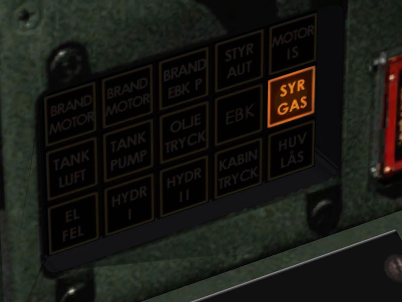
Fig. 86 - Oxygen warning light
Copyright © 2001–2024 Bookmark AB