Flight Manual: Bookmark J-35OE Draken 1.12024-04-04
Features and special effects
Options panel
The first time that you load Draken in Prepar3D an Options panel will be shown. This is where you enable extra features such as the animated control stick and other interior and exterior effects. Your choices will be saved between sessions.
Clicking on Shift-9 will open the Options panel.
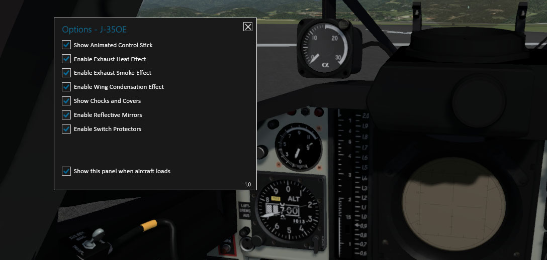
Fig. 88 - Options panel
Sounds
The exterior engine sounds (including the start-up and shut-down sequences) are based on stereo recordings of a Volvo Flygmotor RM6B engine, a license-built Rolls-Royce Avon 200 series engine used in the 35A/B and in the A 32 Lansen. This engine is identical in sound to the RM6C used in 35J.
The interior engine sounds are a mix of synthesized sounds and the exterior sounds. Switch sounds and warning sounds are mostly synthesized but similar to the real sounds.
Sound clips used to create the sound effects are either recorded by Bookmark or in the public domain.
Afterburner
The single-stage EBK-67 afterburner (reheater) adds approximately 20 kN of thrust to the 57 kN dry thrust of the RM6C (Rolls-Royce Avon 300 Mk. 60) engine.
In the real Draken the afterburner was activated by pushing the throttle to a spring-loaded stop beyond the normal maximum (MIL) position.
In this simulation the afterburner must be activated with the Concorde Afterburner/Reheater key command ( Shift-F4 ). It will not be activated by applying full throttle.
The following conditions must be fulfilled to enable the afterburner:
-
Engine speed above 90 %
-
Afterburner fuel valve open
-
Remaining total fuel above 5 %
-
AC power available (alternator bus on)
When the afterburner is activated you will feel a significant thrust boost, and the
NB warning light is lit for a few seconds while the exhaust
nozzle eyelids
open.
To cut off the afterburner, pull back momentarily on the throttle. The NB warning light will light up briefly while the exhaust nozzle closes.
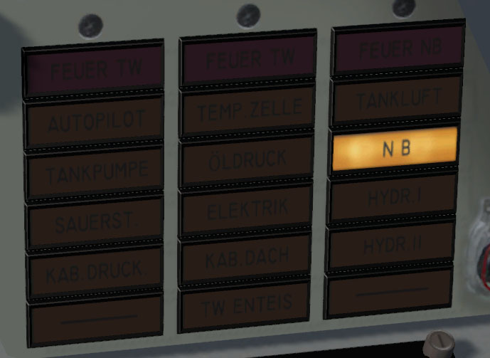
Fig. 90 - Afterburner warning light
The NB warning light is not an indicator for active afterburner. It only lights up when the exhaust nozzle hydraulics are operated and on afterburner malfunction.
Canopy
The canopy is opened with the Select Exit key command (default: Shift-E ). When the canopy is unlocked the canopy warning light KAB.DACH will be lit.
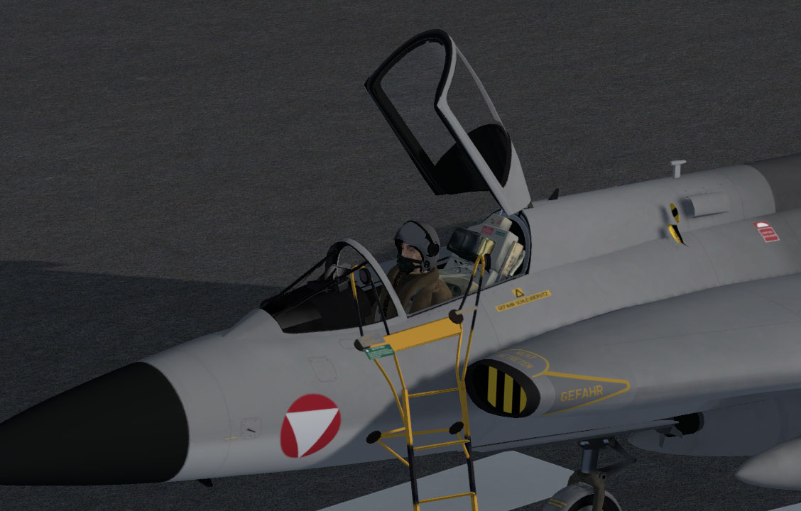
Fig. 91 - Canopy open
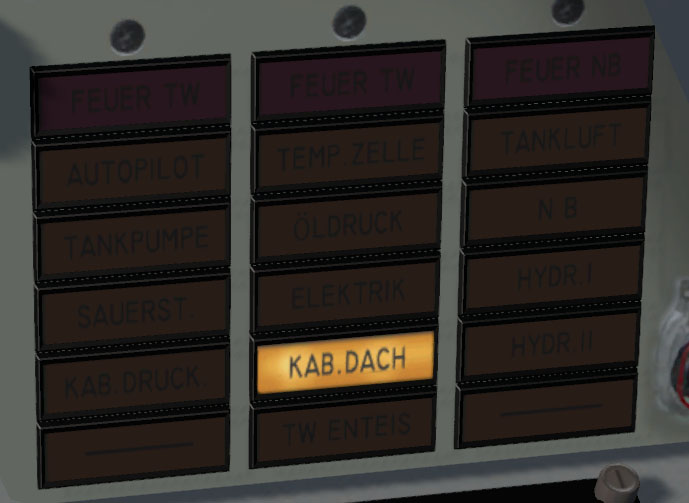
Fig. 92 - Canopy warning light
If the canopy is opened during flight it will detach from the aircraft.
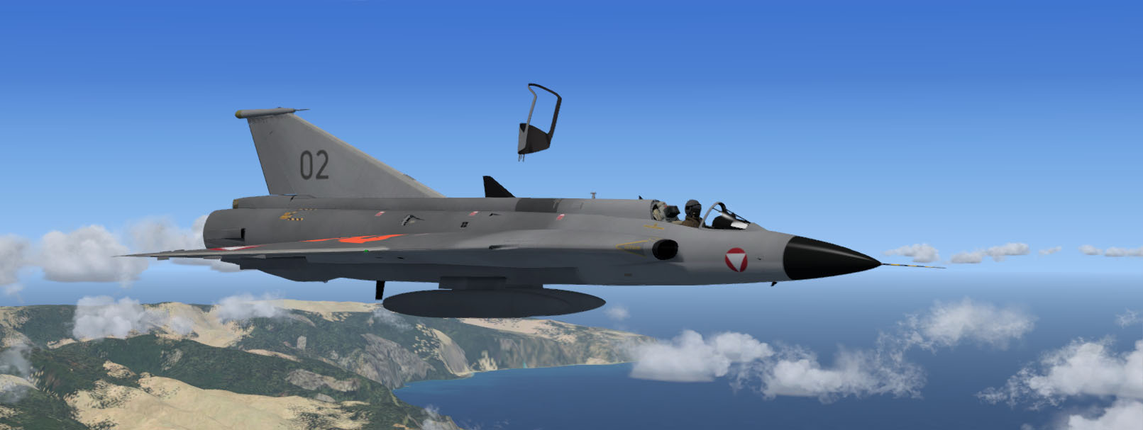
Fig. 93 - Whoops. Here comes a Saab convertible.
Drop tanks
J-35OE can be fitted with two external tanks under the fuselage. The external tanks can be jettisoned with the Drop Tanks 1 key command in Prepar3D or FSX. Two successive keystrokes are needed to arm (unlock) the mechanism and release the tanks.
In the real Draken, a toggle switch on the left side of the canopy frame is used to arm the drop tanks for release, and a button (protected by a red plastic membrane) is pushed to jettison. The arming switch and release button are not functional in this version.
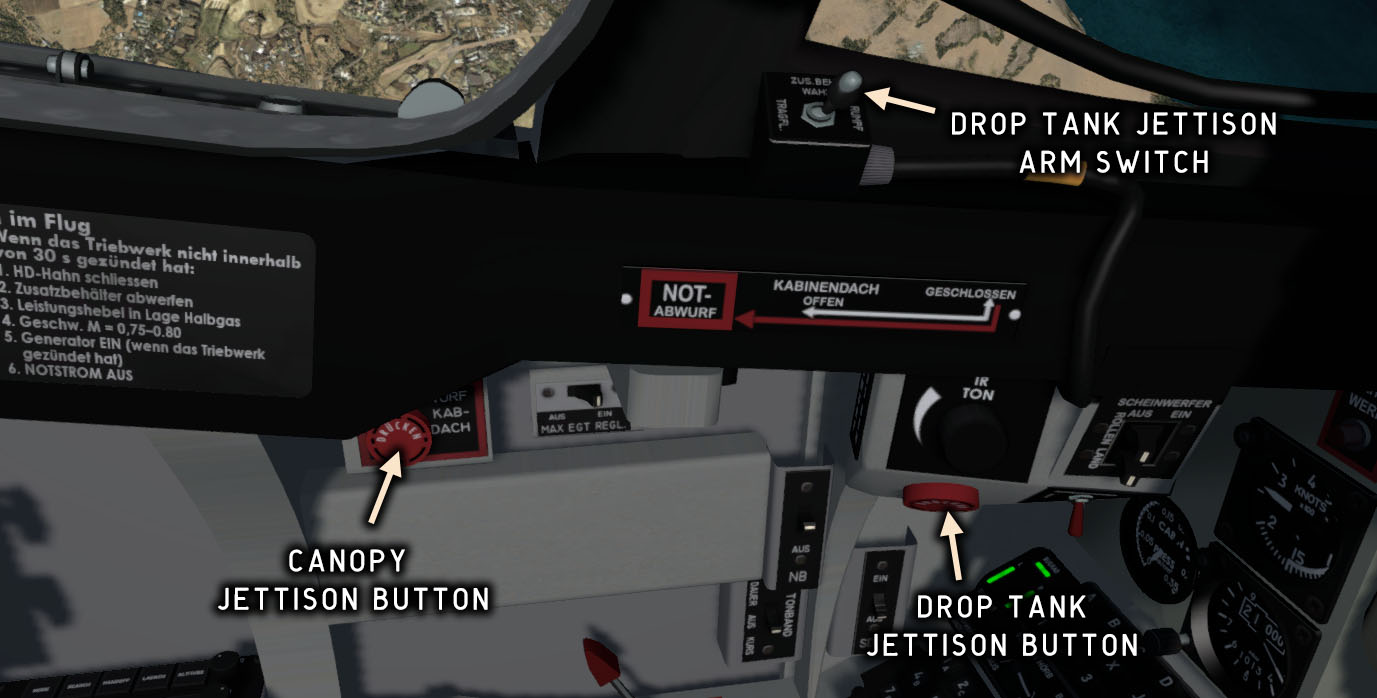
Fig. 94 - Tank and canopy jettison switches
Note that a similar button is used to jettison the canopy. Not a great design choice.
Drag chute
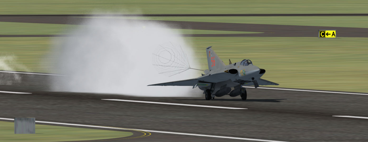
Fig. 95 - Landing with drag chute
The drag chute lever and indicator are located on the throttle console. In the simulation the chute is operated with the Increase Flaps Incrementally key command (F7 ). The first click will deploy the chute, the second will drop it. Draken has no flaps, so this command is used for the chute.
In this simulation you can reset the chute by clicking on the chute indicator.
The drag chute mechanism is completely mechanical and will work without hydraulic and electrical power. The chute lever can only be operated if the throttle is below 90 %.
To prevent damage to the chute cords from the engine exhaust, the chute should be released as soon as ground speed is low enough to use wheel brakes.
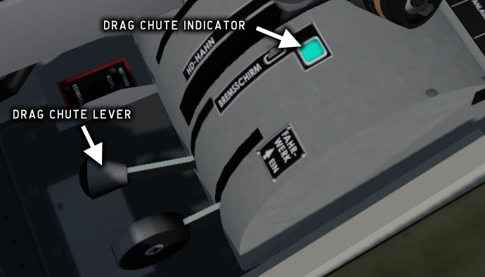
Fig. 96 - Drag chute controls

|
Chute stowed (ready for deployment) |

|
Chute deployed |

|
Chute released (dropped) |
Contrails and smoke
Engine starter smoke
When the engine is started, yellow smoke from the AVPIN (isopropyl nitrate) starter motor will emanate from a valve underneath the left ram air intake.
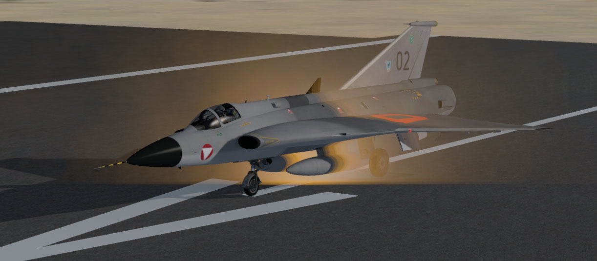
Fig. 97 - Starter smoke effect
Exhaust heat
A very subtle effect of heated air emanating from the engine exhaust. It will increase with thrust and is only visible on the ground.
This effect can be enabled/disabled from the Options panel.
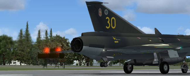
Fig. 98 - Exhaust heat
Exhaust smoke
The RR Avon/RM 6 engines normally do not produce much smoke except on startup and on full throttle. A big smoke trail indicates that fuel is not being completely burnt, usually due to residue or wear in the injection system.
This effect can be enabled/disabled from the Options panel.
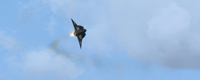
Fig. 99 - Exhaust smoke
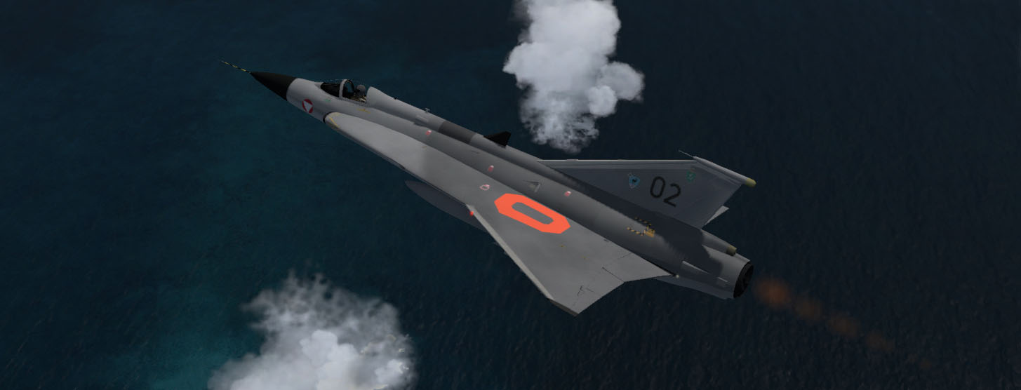
Condensation
Wingtip contrails and wing condensation may appear with high G load, depending on temperature and relative humidity. A contrail will also appear at high altitude and/or air temperatures below -30 °C.
The high-G vapor effect can be enabled/disabled from the Options panel.
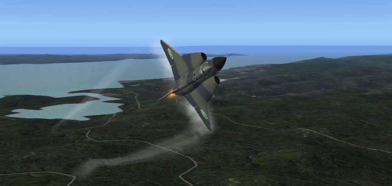
Fig. 100 - Condensation effects in a high-G turn
Chocks and covers
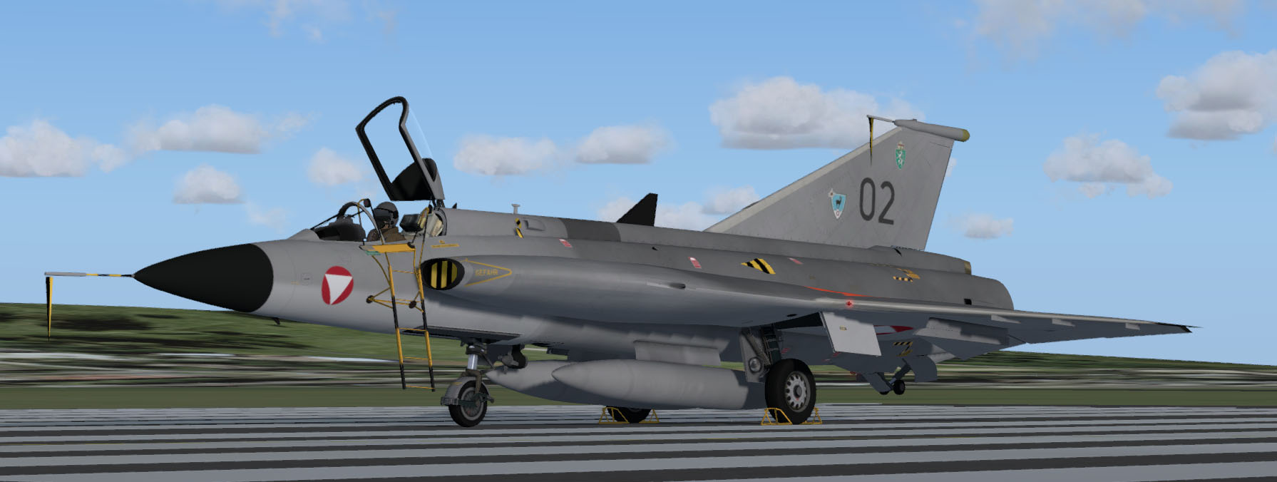
Fig. 101 - Details visible when parked
When the aircraft is parked and the engine is completely shut down (turbine not spinning), additional details such as the ladder, intake and exhaust covers, wheel chocks, etc. will become visible. They will disappear when the engine is started.
This effect can be enabled/disabled from the Options panel.
Pilot animations
G force effects
The upper body of the pilot moves laterally and longitudinally as G force is applied. The head of the pilot turns with rudder pedal input.
Helmet visor
The helmet visor will be raised when the oxygen valve is closed.
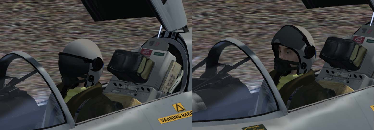
Fig. 102 - The helmet visor
Copyright © 2001–2024 Bookmark AB