Flight Manual: Bookmark J-35OE Draken 1.12024-04-04
Instrumentation
Cockpit layout overview
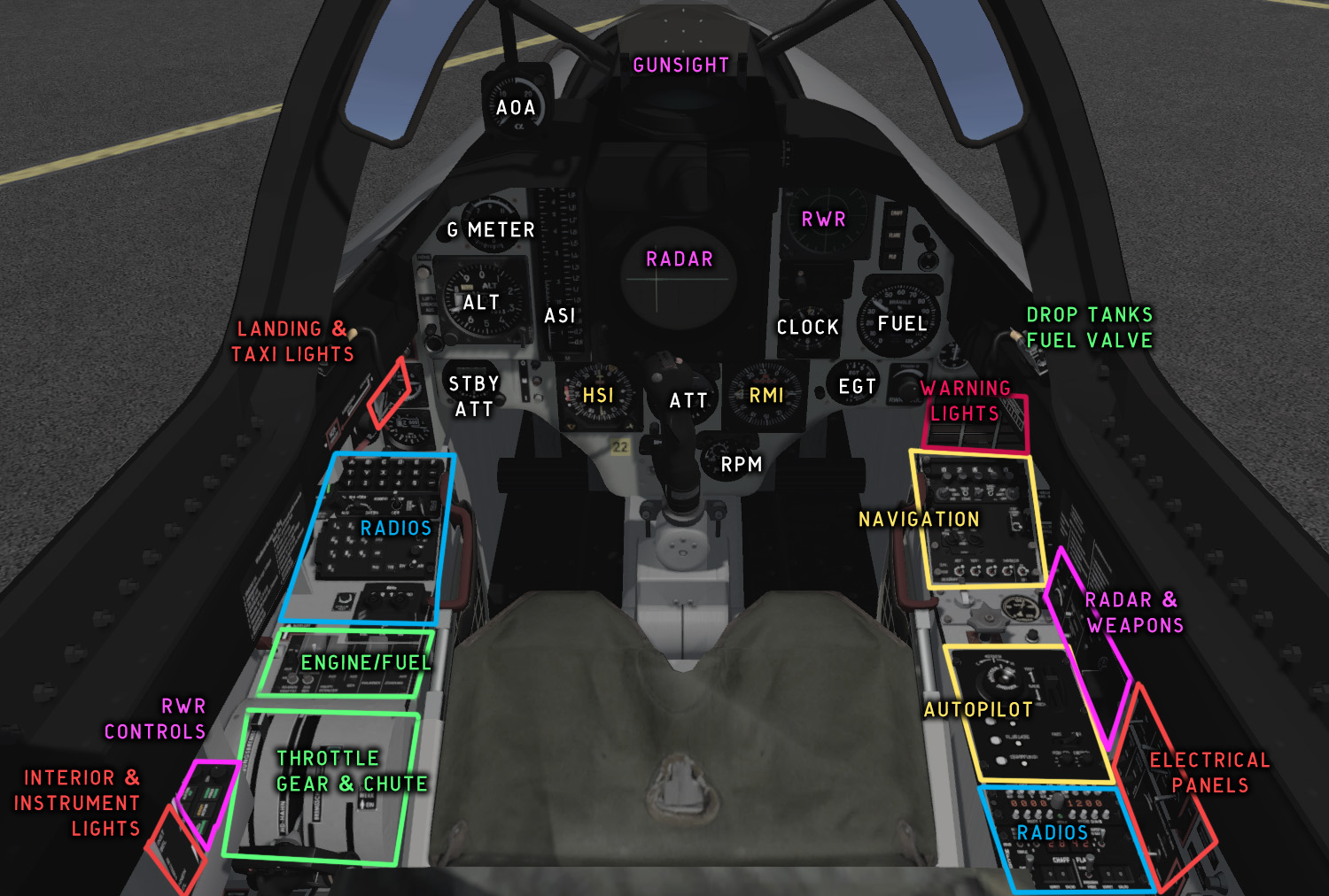
Fig. 33 - J-35OE cockpit overview
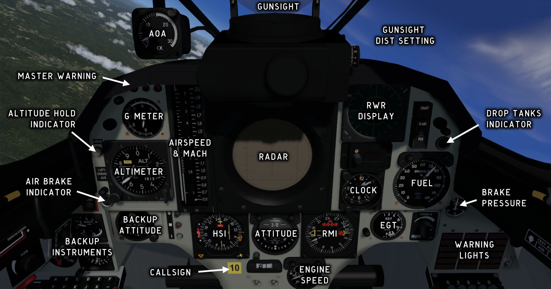
Fig. 34 - Front instrument panels
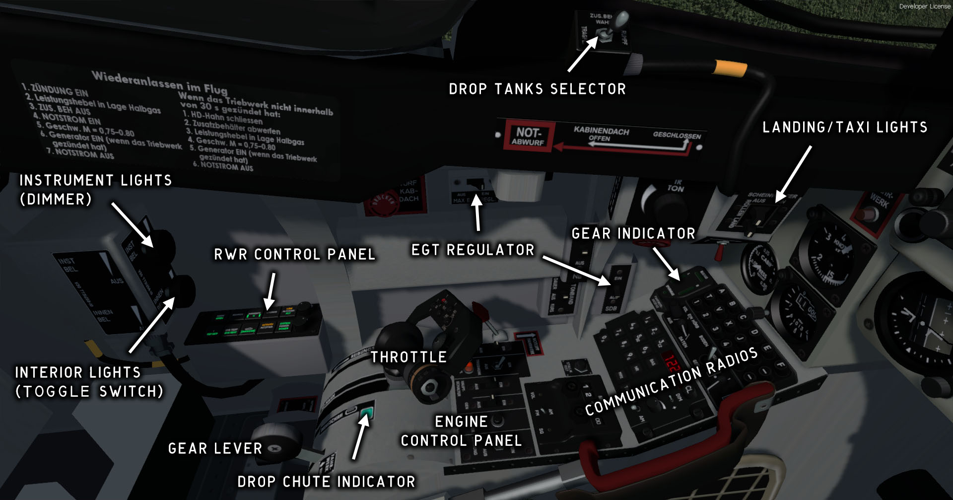
Fig. 35 - Left side panels
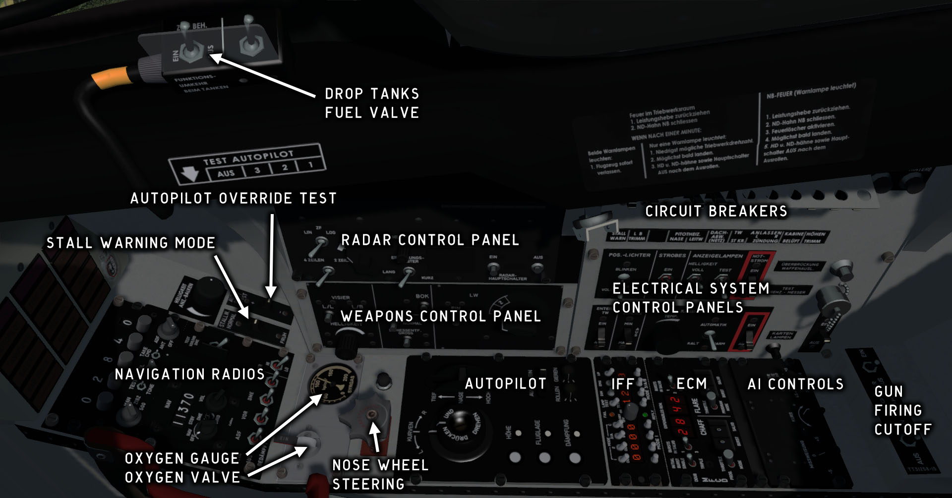
Fig. 36 - Right side panels
Airspeed indicators
Airspeed and Mach indicator
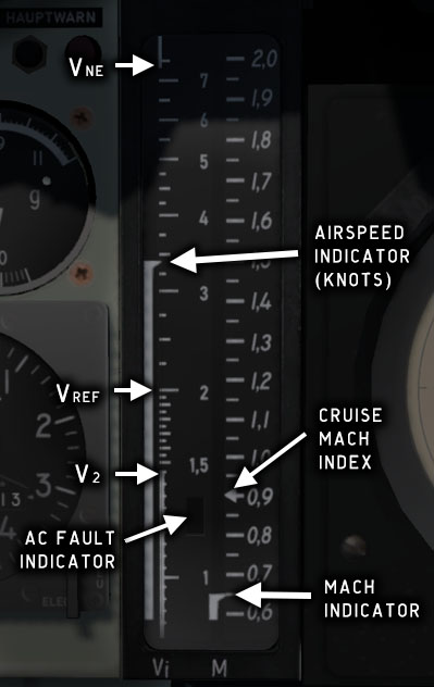
Fig. 37 - Airspeed/Mach indicator unit
The airspeed indicator is powered by the flight computer, which calculates KIAS and Mach values from the nose pitot tube pressure.
The Mach scale is linear from M 0.5 to M 2.0 and has an index at cruise Mach (M 0.9).
The Vi scale is linear from 80 kt to 190 kt and logarithmic from 190 kt to 750 kt. The scale has indices for V2 (145 kt), Vref (200 kt), and VNE (730 kt).
A white rectangular field on the lower part of the airspeed scale indicates AC bus failure. The indication will disappear when the alternator bus is switched on and the engine speed is at least 28 %.
Backup airspeed indicator
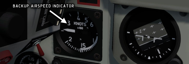
Fig. 38 - Backup airspeed indicator
The backup ASI is located on the left knee panel and shows indicated airspeed from 50 kt to 700 kt. The backup ASI is mechanical and is connected to the stab fin pitot tube.
Altimeters
Main altimeter
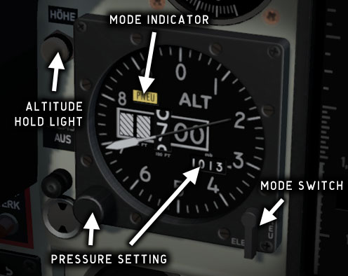
Fig. 39 - Altimeter
The altimeter shows the pressure altitude in feet. The value is calculated by the flight computer when in mode ELECT. If the mode selector is set to PNEU, the computer is bypassed and the altitude reading is taken from the aneroid.
The needles are driven by an electrical stepper motor, which means that needle movement is not fluid but in small increments.
To set the altimeter, place the cursor on the pressure setting knob and rotate the mouse wheel. The pressure setting is in millibars (hPa).
1 Atm = 1013.25 mb (hPa) = 760 Hg.
Backup altimeter
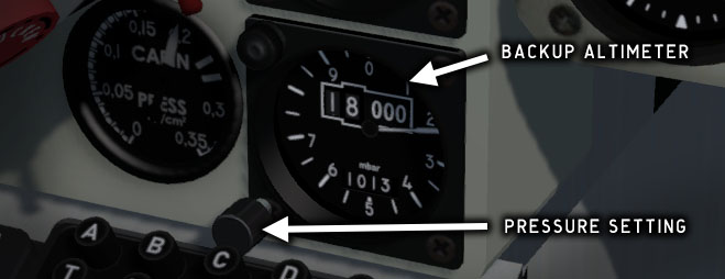
Fig. 40 - Backup altimeter
The backup altimeter is located on the left knee panel. The indicator is mechanical and directly fed from an aneroid. It is completely separate from the main altimeter and has its own pressure setting.
Attitude indicators
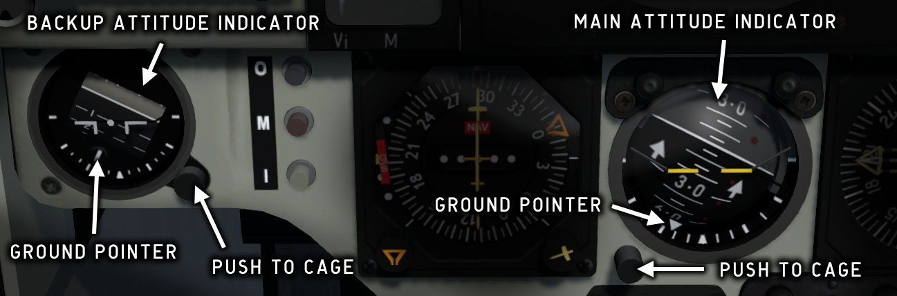
Fig. 41 - Attitude indicators
The main attitude is electrically driven and monitored by the flight computer. A rotating ball indicates pitch and bank. A bank indicator ring with a triangular roll index (ground pointer) indicates bank angle and the direction to the ground. A red error indicator is visible when the instrument is not powered.
The backup attitude indicator is connected to a separate gyro. A rotating cylinder indicates pitch and bank. A bank indicator ring with a roll index (ground pointer) indicates bank angle and the direction to the ground. A red error indicator is visible when the instrument is not powered.
AOA indicator
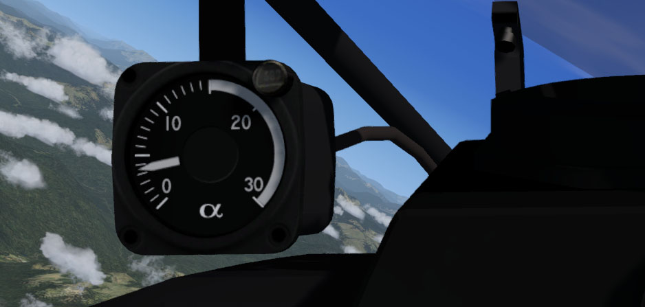
Fig. 42 - AOA indicator
The AOA indicator shows the current alpha angle of attack, which is the angle between the wing chord line and the current movement vector. Drag increases quickly with increasing alpha angle, so this indicator is crucial for maintaining control of the aircraft.
The Stall warning system will alert the pilot at a preset angle of attack.
G-force indicator
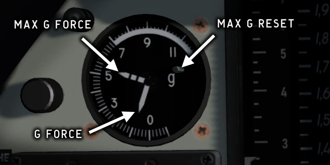
Fig. 43 - G-force indicator
The g-force indicator shows acceleration force in the range -1.5 to +11.5 G. The indicator has a maximum needle which is reset by pushing a small button on the dial.
An acoustic warning signal is triggered at approximately +6 G.
The g-force indicator is disconnected when the aircraft is on the ground.
Chronometer
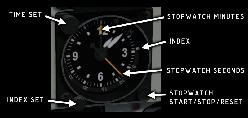
Fig. 44 - Chronometer
The aircraft chronometer is electrical and shows the current local time in hours/minutes. It has a stopwatch function and a moving index used to monitor flight time.
Before take-off, turn the index ring to align the index with the minute hand. The duration of the flight can then be read from the position of the minute hand vs. the index.
The stopwatch pushbutton will successively start, stop, and reset the stopwatch.
Cabin pressure indicator
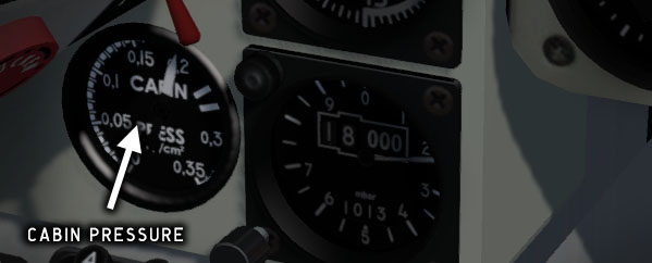
Fig. 45 - Cabin pressure indicator
The cabin pressure indicator is located on the left knee panel. It shows the pressure difference between ambient pressure and cabin pressure.
Cabin air pressure is automatically regulated by a pressure regulator. The pressure difference will be zero up to 10000 ft (3000 m), and will then increase with altitude to a maximum of ~0.25 kp/cm2 (24.5 kPa) at 21000 ft (6400 m).
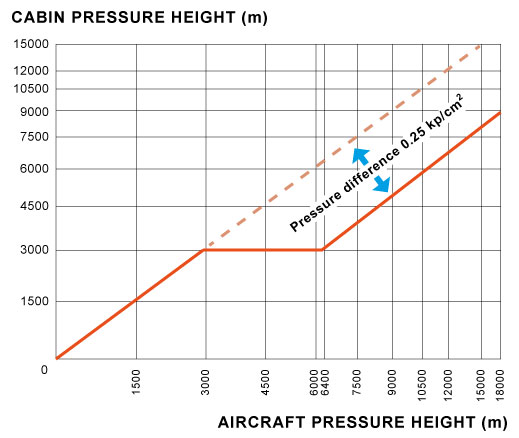
If the pressure difference exceeds 26 kPa, the cabin pressure warning light KAB.DRUCK. will be lit.
Warning and indicator lights
Warning lights panel
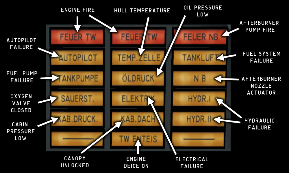
Fig. 47 - Warning lights panel overview
-
The hydraulic system warning HYDR.II will light up momentarily if you make large stick movements when the engine is running at ground idle. This is normal and only indicates that hydraulic pressure is insufficient to deflect the elevons fully. The EPU will also be extended momentarily while this warning light is lit.
-
The fuel pump warning TANKPUMPE will be lit when AC power is off, unless fuel is provided from the drop tanks (drop tanks fuelled and valves open). In that case, fuel pressure will be sufficient even without the fuel pump.
-
The afterburner warning light NB indicates afterburner malfunction but is also lit when the exhaust nozzle
eyelids
are changing position, and when the nozzle overheating protection system (SDB) is active. It does not indicate that the afterburner is active. See also Engine. -
The AUTOPILOT warning light indicates autopilot failure. It will also be lit if you switch off the autopilot main switch, or when you override the autopilot.
Master warning
The two master warning lights (HAUPTWARN) will blink if any of the other warning lights are lit, with some exceptions:
-
The engine deice indicator light (TW ENTEIS) will not trigger a master warning.
-
The NB warning light will only trigger a master warning if it is caused by an afterburner malfunction.
-
When the emergency bus is switched on, the electrical failure warning (ELEKTRIK) will still be lit, but the master warning lights will not be lit.
-
The Fuel System (TANK LUFT) warning sometimes lights up for a few seconds when the system switches from external to main fuel tanks. This will not cause a master warning.
Push the black button between the master warning lights to acknowledge the alarm. The lights will then stop blinking and show a steady light.
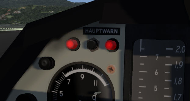
Fig. 48 - Master warning lights
Gear warning
The gear warning light (FAHRWERK) will blink while the main gear is being extended or retracted. It will also blink if throttle is reduced at low altitude with the gear not extended. See also Landing gear.
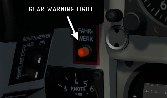
Fig. 49 - Gear warning light
Copyright © 2001–2024 Bookmark AB