Flight Manual: Bookmark J-35OE Draken 1.12024-04-04
Radar and weapons
Radar system
The radar simulation in this version is not anywhere like the real targeting radar in J-35OE, although the range and scan modes are roughly similar to the real thing. The radar screen will display AI and multiplayer aircraft, but no ground objects. Targeting is not implemented.
In J-35OE the radar scope was normally covered with a hood to shield from reflections, and the pilot was flying head down when looking at the scope. The presentation was therefore also projected on the gunsight HUD.
In this simulation, the scope is uncovered for convenience and the image is not projected on the HUD.
Overview
The radar in J-35OE is basically the Ericsson PS-03/A used in the Swedish J 35D version but with some adaptations made for the Austrian Air Force.
The radar has two distance ranges, 8 Nm or 20 Nm, and and 4 different sweep programs for 40°–120° degrees scan width. Antenna height (elevation) can be adjusted, although this has no effect in the simulation.
The radar screen presentation mode can be either B-scope or "Tactical Mode" (F-scope). Switching between these modes was automatic depending on the target acquiring and weapon delivery phases. In this simulation you can toggle between these presentation modes with the ASI switch on the radar control handle.
The radar will only transmit when the aircraft is off the ground. When the nose gear is compressed, the radar will automatically be switched to silent (non-transmitting) mode.
Radar screen
In B-scope mode, the horizontal potition of the target echo represents bearing (azimuth) and the vertical coordinate represents the target altitude. Antenna elevation is indicated with a horizontal line.
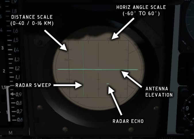
Fig. 60 - Radar screen, B-scope presentation mode
In F-scope (tactical) mode, the horizontal position of a radar echo represents bearing and the vertical position represents target elevation (vertical angle relative to aircraft).
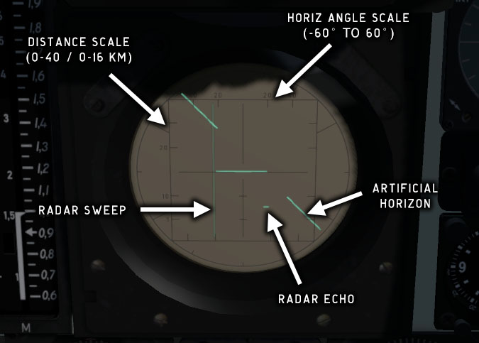
Fig. 61 - Radar screen, F-scope (tactical) presentation mode
An artificial horizon is displayed as a split horizontal line in F-scope. The outer segments indicate roll and pitch. The center segment will be static in ANT FPL mode (see radar control handle below), otherwise it will indicate roll angle but not pitch.
Do not rely on the radar scope artificial horizon for attitude indication. The antenna height indicator line in B-scope can be mistaken for the artificial horizon, giving the impression that the aircraft is flying straight and level.
Radar control panel
The radar control panel is located on the right side wall of the cockpit.
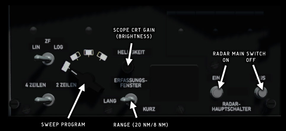
Fig. 62 - Radar control panel
The radar has 4 different sweep sector programs and 2 scan ranges (8/20 nautical miles).
The HELLIGKEIT knob is used to dim the intensity of the CRT scope.
The ZF LIN/LOG and 4 ZEILEN/2 ZEILEN switches have no function in this simulation.
Weapons control panel
The weapons control panel is located on the right side wall of the cockpit. The panel contains controls for the gunsight and for selecting and activating weapons.
This simulation does not include functional weapons.
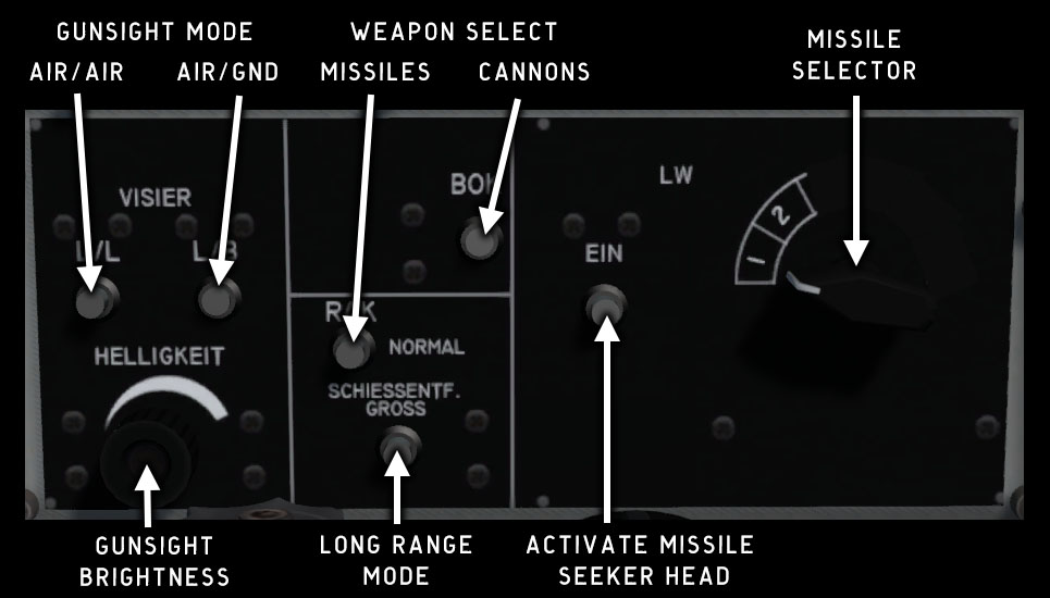
Fig. 63 - Weapons control panel
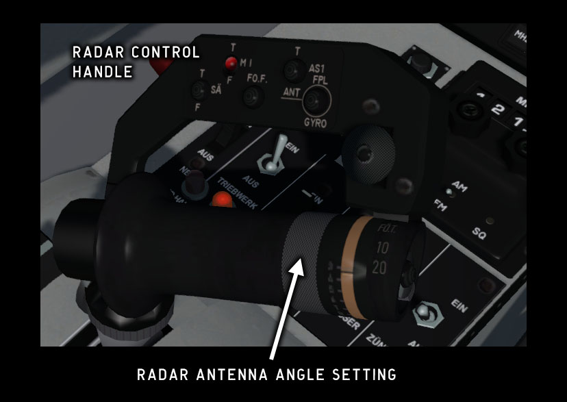
Radar control handle
The radar control handle is located on the throttle handle. The switches and the mini-joystick
on the handle are used to control
radar mode and targeting functions. The throttle grip can be rotated to set the antenna
angle (not implemented).
Use Shift-3 to open a 2D panel version.
SÄ
Toggles radar transmitting on (T) or off (F)
MI
Toggles display of ground info (not functional)
FÖR
Select next target (not functional)
AS1
Toggle B-scope / F-scope presentation
ANT FPL/GYRO
Set radar antenna to be fixed or gyro-stabilized (always horizontal)
Weapons
Loadout configuration
This simulation does not include functional weapons. Missiles can be added to the exterior model, but they cannot be deployed.
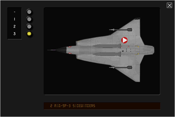
Fig. 65 - Loadout configuration panel
J-35OE has two 30 mm Aden cannons and 2 hardpoints for A/A or A/G missiles.
In this simulation there are 4 preset loadout configurations.
|
Preset |
Description |
|---|---|
|
- |
Clean aircraft (no loadout) |
|
1 |
1 AIM-9P-3 Sidewinder on left wing pylon |
|
2 |
1 AIM-9P-3 Sidewinder on right wing pylon |
|
3 |
2 AIM-9P-3 Sidewinders |
Gunsight
The HUD gunsight in J-35OE was integrated with the avionics and radar systems and could be used in either radar-aided or optical mode. It provided aiming information for A/A missiles in radar-aided mode, and for the cannon and A/G missiles in optical mode.
This simulation only includes the optical gunsight mode (diamonds and pipper). If cannons are selected, the gunsight will use gyro aided aiming. If missiles are selected, the reticule will be static.
The targeting range (radius of the gunsight reticle) can be adjusted with the knob on the right side of the gunsight assembly.
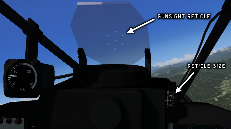
Fig. 66 - Gunsight in J-35OE
Copyright © 2001–2024 Bookmark AB